Logitech Quickcam Pro 3000 Long Exposure Modification
Making the Control Circuit
My circuit is a little different from Martin's. For one thing, he used a parallel port to control the circuit from a PC computer. I'm a diehard Mac user, so parallel ports are right out. While the option of serial ports is available, I didn't feel like buying a $70 USB to Serial converter, so I used two manual switches (one for shutter and one for exposure), with no computer control. Another difference is that I used different pins on the 4066 than Martin did, corresponding to a different internal bilateral switch on the 4066. The reason I did this is that the two unused switches must be grounded, and the simplest, cleanest way to do this is to ground the two switches whose control lines are right next to the ground pin on the 4066. Martin didn't go this route. It's an entirely arbitrary decision and doesn't make any difference in the end.
NOTE: In June, 2003, after using this modified camera with a physical control switch for a year, I extended the mod to allow automatic computer control from my Mac. Details are provided at the end of the description of the camera modification.
|
|
 |
Circuit diagram.
Click to enlarge.
|
 |
PC board circuit layout.
Click to enlarge.
|
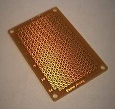 |
Take a small piece of pc board...
|
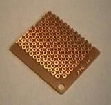 |
...and make it even smaller. I laid things out on my circuit diagram in advance so I knew exactly where I wanted them by the time I arrived at the pc board.
|
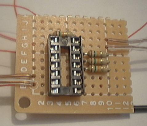 |
The socket and four resistors inserted into the pc board, along with two wires on the right (USB +5V and fan power) and two wired on the left (USB ground and fan ground). There are also a bunch of wires visible that are already soldered underneath. The fan power wire feeds through a toggle switch prior to connecting to the fan so that I have manual control over the fan.
Click to enlarge.
|
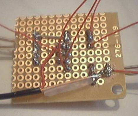 |
The soldering on the underside of the circuit. This is a little complicted to interpret. It's probably easier to just refer to the circuit diagram and circuit layout. Aside from the four copper wires protruding from the opposite side, notice that there are six red wires and the black shielded cable which splits into two wires (one of which is also red). Four of the six red wires go to the four connections on the webcam circuitboard. Two go to the manual shutter control switch, and the two wires from the shielded cable go to the remote control (for manually controlling the exposure time). The big soldered chunk on the left is a connected hunk fed from the USB +5V. Likewise, the big solder chunk in the lower right grounds out to the USB ground.
Click to enlarge.
|
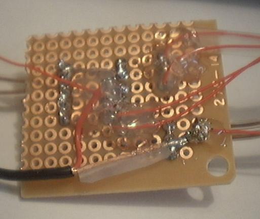 |
I went ahead of doused the circuit in hot glue, just to make sure nothing would break off or short circuit at a later time.
Click to enlarge.
|
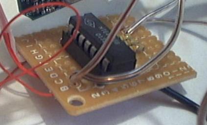 |
Here is a picture of the 4066 IC inserted into the socket after everything else is finished. The 4066 is extremely static sensative, so inserting it into the socket was the very last step I performed.
Click to enlarge.
|
 |
A fairly useless picture, but this shows how the two USB connections were soldered and then glued to the USB lines on the circuitboard. These connections must be made on the opposite side of the circuitboard from the previous modification (you can see the CCD at the bottom of the picture). There are 5 wires and a shield off to the side. The +5V is the red wire (wire number 1) and the ground is either of the black wires or the shield (wire numbers 2, 4, and the shield). They're all electrically connected (easily verified with a multimeter), so it doesn't matter which one you choose for the ground connection. I used wire number 4 myself.
Click to enlarge.
|
