Logitech Quickcam Pro 3000 Long Exposure Modification
Making the Enclosure and the Remote
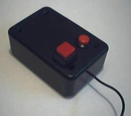
The remote control is used to manually control the exposure time. Most other people, including Martin, control the webcam from a computer, opening and closing the shutter and exposure circuits over a parallel or serial connection. I chose manual control. There are two pushbutton switches on the remote which are wired in parallel. One is momentary (the switch is only closed while I hold my thumb down on it and then it opens when I release my thumb) and the other is on/off (push once to close the switch, push again to open it). I did this so I could do brief exposures (half a second up to a few seconds) using the momentary switch and could do long exposures (from several seconds and up) using the on/off switch.
NOTE: In June, 2003, after using this modified camera with a physical control switch for a year, I extended the mod to allow automatic computer control from my Mac. Details are provided at the end of the description of the camera modification.
|
|
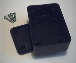 |
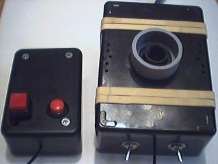
The remote box...
|
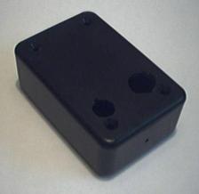 |
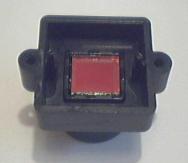
...with two holes drilled for the two pushbutton switches...
|
 |
...with the switches installed. It's worth noting that in both boxes I tied a knot in the shielded cable inside the boxes that wouldn't slip through the hole that allows the cable to pass through the side of the boxes. This acts as a strain relief for the wire so that there will always be forceless slack inside the box. As a result, there is no physical strain put on the solder joints at either end of the cable if the cable is tugged at.
|
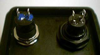 |
The two switches from the inside of the box...
|
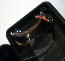 |
...connected to the shielded cable and soldered for good measure.
|
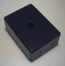 |
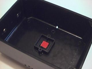
Here is the camera enclosure box, showing some ventilation holes on the side (I eventually added a few more), a central hole for the light path, and a series of holes in one end for mounting the two toggle switches (shutter and fan control) and to allow the shielded cable to the remote out of the box.
|
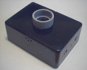 |
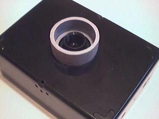
The camera will be mounted on the telescope using a Mogg adapter which screws into the lens holder (which will eventually protrude from the central hole). I was worred about the strain that might be put on the Mogg adapter joint so I put this piece of gray pvc tube around the central hole. It is just wide enough to sit against the thick base of the Mogg adapter and is just tall enough that when the Mogg adapter is screwed in tightly the base of the Mogg adapter will rest firmly against this pvc ring. The pvc ring is attached to the camera box using superglue.
|
 |
Remember that the lens holder was removed from the webcam circuitboard? Here it is, showing the ir filter mounted inside it. I decided not to remove the ir filter for the time being. I can always remove it later if I chose to do so.
|
 |
The lens holder is inserted into the central hole so that the threads protrude through the hole to the outside of the box. The len holder is attached to the camera box from the inside with superglue.
|
 |
Here is the camera box showing the lens holder sticking through the central hole from the interior of the box.
|
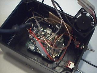 |
The mod is almost entirely complete. The circuitboard is screwed back onto the lens holder, the two toggle switches are installed through the ends of the camera box and have been soldered to the shutter and fan control wires, and the fan has been soldered to its power wire (coming from the fan switch) and its ground wire, which goes to the ground contact on the pc board. The pc board rests nicely inside the camera box. I didn't even hold it in with tape. The springlike action of cramming all the wires into the box holds it firmly against the side of the box. It isn't going anywhere. The only task that remains is to attach the fan to the copper plate that will serve as the back of the camera.
|
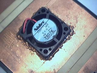 |
Here is the fan hot glued into its hole in the copper plate. I made a solid airtight seal all the way around the fan, so as to insure that any air pulled out of the box by the fan has to be pulled in through the ventilation holes in the front of the camera, to make sure there is a constant flow of air over the circuitboard rather than a pointless cycling of air in the back of the box.
|
 |
Here is the completed mod. As you can see, I added a few more ventilation holes, and presently hold the back on using rubberbands. Although the camera box had shafts for screws, they aren't threaded, so I'm not sure how to attach the back using that method. Rubber bands are fine for now.
|
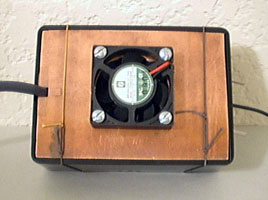 |
Here is what the back looked like after I replaced the small fan with the larger one. This one was large enough that I could mount it with nuts and bolts, thus avoiding the difficulty of hot-glueing the thing in place.
|
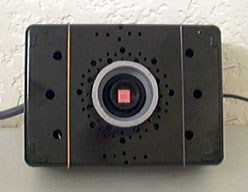 |
I also added tons of ventilation holes on the front of the box. I wanted to keep the holes as localized around the middle as possibly, to maximize the amount of air that would be drawn directly over the circuitboard, but I was disappointed with the airflow, so I added some large holes off to the side as well.
|
