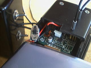
Logitech Quickcam Pro 3000 Long Exposure ModificationSubsequent Modification to Permit Mac Exposure Control and Amp-off CircuitAfter using the camera with the physical switches for about a year I finally decided to make an attempt at designing and implementing a computer control system. Windows users of long exposure modified webcams have been doing this from the start by using the various pins on the parallel port as switches. Custom software that is specifically written to control these modified webcams set the voltages on the pins of the parallel port either high or low, thereby toggling exposure control on the camera. One nice thing about a parallel port is that it has several pins which are all functionally distinct from one another, in "parallel". This allows multiple switches to be controlled. This means both the exposure and the shutter can be controlled from the computer. Likewise, there are further modifications that can be performed. For example, the on-chip amplifier can be disabled, which reduces corruption of long exposure images, but this amplifier must be switched on and off. Another mod controls the even and odd rows of the CCD independently, allowing one set of rows to gather a long exposure while the set of rows is read out more frequently and used for telescope guiding. None of this is possible using a parallel port on a Mac since Macs don't have parallel ports. Macs used to have serial ports, and while they have all gone to USB now, it possible to get a USB/Serial converter and get a serial port on a Mac. However, serial ports do not have several independent pins. This limits the possibilities that are available using a serial port's pins directly. Instead, I resurrected my Pontech SV203 serial-controlled servo-controller board from my Visorbot project. The board costs $60 but I already had it lieing around. The USB/Serial converter cost about $20 or $30. How do I use a servo-controller to control the camera? The SV203 is an incredible little board. It can control up to eight servos and has five analog/digital input pins for reading sensor input. These features aren't too useful for the long exposure camera modification (although it would be neat to put a thermistor inside the camera so my software can read the temperature inside the camera body). However, another feature is that the servo control pins (which usually send modulated signals to control a servo's position) can be reconfigured to hold a constant high or low voltage, just like a switch, or more accurately, like a transistor since switches are open or closed while transistors are high or low, generally speaking. For my new computer-controlled modification I simply cut out the physical switch and plugged the switch's wire into one of the pins on the SV203. Then I upgraded my existing custom-made image-capturing software to access the SV203 over the serial port and to send simple messages to the SV203 that tell it when to set the corresponding pin to high or low voltage and this controls the camera's exposure. As with my previous setup, when an exposure ends, the image is automatically transferred by the camera to the computer over its own USB connection. My software is already set up to detect the incoming image and save it to disk. That part of the program didn't have to be altered at all, only the method for controlling the exposure. There are two advantages of have the computer control the exposure instead of using a physical switch. The first is that the computer can ensure that a set of images are all of precisely the same exposure time. This is important for image-stacking. The second advantage is that I can write my software to capture a batch of images. This allows me to tell the computer to take exposures repeatedly for a long time without constant intervention on my part. This is revolutionary for me. Using my old design I had to physically start and stop every exposure with the physical switch. If I took exposures for an hour I had to sit there click-click-clicking for an hour. Now I can go do something else with that time.
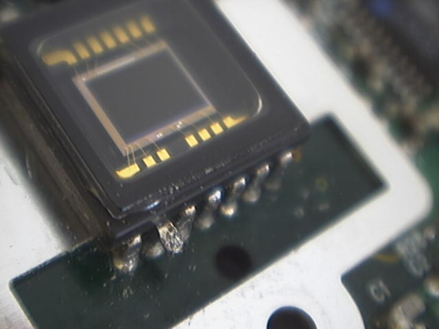
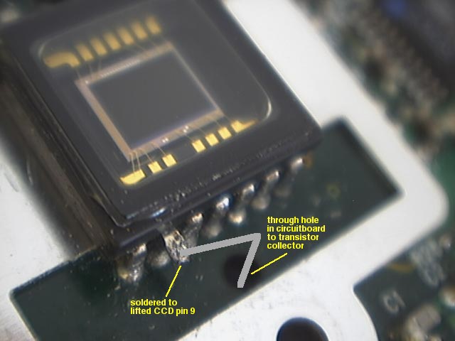
I also advanced the modification of the camera circuitry to allow the on-chip amplifier to be disabled during a long exposure. The amp introduces a gradient glow into long exposures that is best dispensed with entirely by disabling the amp. However, in the case of the Quickcam Pro 3000, disabling the amp also disables the webcam. Therefore it is necessary to only minimize the power to the amp, not turn it off completely. Steve Chambers website (referenced on the first page of my mod description) has a technical image showing the design of this circuit.

Contine this way if you would like to see a set of darkframes that demonstrate the effectiveness of the amp-off mod and compare this camera to the Philips Vesta 675. Fin! |
||||||||||||||