|
|
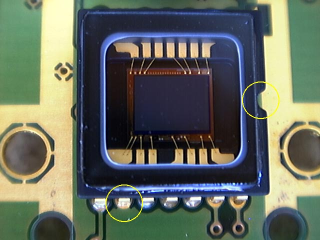 |
A closeup of the CCD. Pin 9 is one pin in from the left on the bottom. You can find it easily be realizing that pin 1 is just counter-clockwise from the notch in the end of the CCD chip and that the pins are enumerated counterclockwise.
Click to enlarge.
|
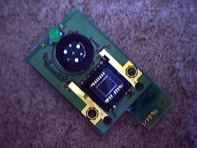 |
I cut the corner out of the bottom of the board. The transistor will be superglued to the remaining corner with the three leads hanging off the cut corner. The lead next to the CCD will be bent toward the lifted pin and soldered to it. The right lead will be bent under the board and soldered to the remaining piece of the pin protruding through the bottom of the board. The central lead is the control lead.
I also broke the green LED off later so its light would leak into the CCD and corrupt the long exposures.
Click to enlarge.
|
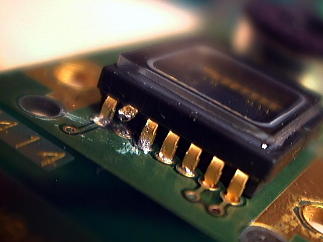 |
I cut pin 9 by literally sawing through it with an x-acto blade. It took a while. Then I folded it up so it would be easy to solder to.
Click to enlarge.
|
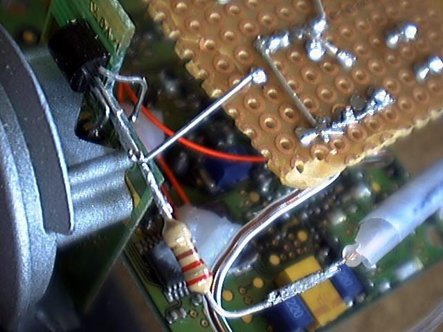 |
Although this image is taken after the camera has been reassembled, it primarily shows how I mounted the transistor on the CCD board and wrapped the three leads to their appropriate locations. Notice that the central control lead goes through a 220 Ohm resistor before going to the main control wire. Likewise, a wire connects the central lead the circuit board to a 15K Ohm pullup resistor.
Click to enlarge.
|
